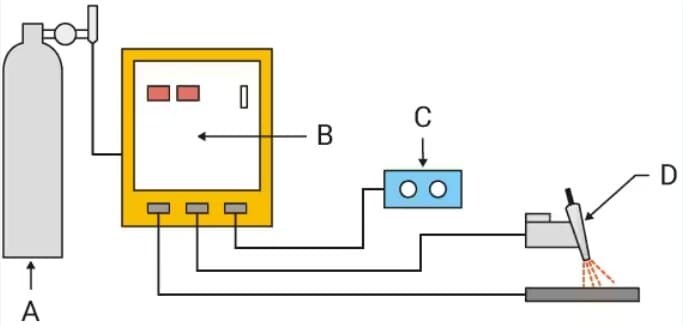
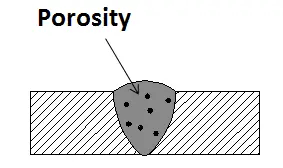
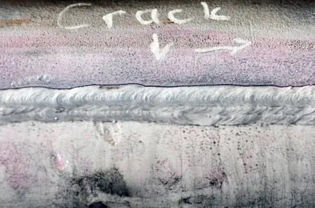
Tungsten Inert Gas (TIG) welding is prized for clean, precise welds — but it’s also unforgiving. Small mistakes in gas, torch handling, cleanliness, or machine settings show up immediately in the bead. Below is a practical, engineer-friendly guide to the ten most common TIG problems, why they happen, and how to fix them. At the end you’ll find a short testing checklist and FAQs to help you verify weld quality. (Sources for the technical guidance and testing methods are listed inline.)

Quick overview — the 10 problems:
Poor gas coverage (porosity / contamination)
Wrong polarity or balance when welding aluminum
Grainy or contaminated bead (filler/base contamination)
Lack of fusion (insufficient root penetration)
Craters and crater cracking at weld stop points
Dirty base metal or filler rod contamination
Tungsten contamination or balling
Overheating / burn-through on thin materials
Excessive weld color / oxidation (stainless & aluminum)
Arc wandering or unstable arc (poor arc control)
The list above consolidates common field failures and remedies recommended in industry TIG guides and equipment application notes.
I. For each problem: what to look for and how to fix it
1) Poor gas coverage (porosity, surface contamination)

What you’ll see:
Tiny pinholes or bubbles in the weld bead
Dull gray surface or soot on stainless/aluminum
Arc flickering or unstable
Why it happens:
Incorrect shielding gas or flow rate
Gas leaks at fittings or torch connections
Drafts or excessive gas velocity causing turbulence
Damaged torch components (cracked cup, loose collet body)
Detailed Fix:
Check gas type: Use 100% Argon for TIG on steel, stainless, and aluminum. Helium or Ar/He blends can help for thick aluminum but are unnecessary for most work.
Adjust flow rate: 12–20 CFH is typical for indoor TIG. Too low → porosity; too high → turbulence. For open areas or large nozzles, increase slightly to 20–25 CFH.
Leak test your gas line: Apply a mild soap-water mix at hose joints, regulator, and torch connections. Look for bubbles.
Inspect torch parts: Replace worn O-rings, cracked cups, or bent back caps. Ensure collet body threads are tight.
Shield the weld zone: Block fans or drafts. If outdoors, use barriers or a temporary enclosure.
Post-flow timing: Set 5–10 seconds of post-flow (longer for thicker tungsten). This protects both tungsten and weld pool while cooling.
2) Welding aluminum with wrong polarity / balance
What you’ll see:
Black soot, oxide “islands,” or dull surface
Poor wetting and inconsistent puddle
Tungsten overheating or excessive balling
Why it happens:
Detailed Fix:
Set correct polarity: For aluminum → AC (alternating current); For steel/stainless → DCEN (direct current electrode negative).
Adjust AC balance: Start around 70% EN / 30% EP (Electrode Negative / Positive); Increase EP to 35–40% if oxide remains; Reduce EP if tungsten overheats or balls excessively.
Fine-tune AC frequency: 100–120 Hz gives a narrower, more stable arc for fillet welds; 60 Hz gives a softer, wider arc for thick materials.
Pre-clean aluminum: Remove oxide layer using a stainless brush or mechanical abrasion immediately before welding.
Use proper tungsten: 2% lanthanated or ceriated (blue or gray tip) holds shape better on AC.
3) Grainy / inconsistent bead (filler-metal or feed issues)
What you’ll see:
Why it happens:
Detailed Fix:
Clean filler rods: Wipe with acetone before use; store rods in sealed tubes to prevent oxidation.
Check filler alloy: Match to base metal — e.g., ER70S-2 for mild steel, ER308L for stainless, ER4043 or ER5356 for aluminum.
Feed technique: Feed filler gently into the front edge of the puddle, not directly into the arc. Keep filler tip inside the gas shield.
Control heat input: Overheating creates grainy texture; lower current or increase travel speed slightly.
Arc length: Keep arc tight — about 1–1.5× tungsten diameter away from the puddle.
4) Lack of fusion (root or toe lack of penetration)
What you’ll see:
Why it happens:
Detailed Fix:
Increase amperage: For mild steel, use ~1 amp per 0.001" of thickness as a baseline. Example: 120 A for 1/8" steel.
Shorten arc: Maintain 1–2 mm between tungsten and puddle for a focused, penetrating arc.
Adjust torch angle: Keep 10–15° push angle; direct more heat into thicker material if joint is uneven.
Improve joint fit-up: Bevel thick joints; maintain tight, consistent root gaps.
Use pulse TIG (if available): Set pulse frequency 1–2 Hz for manual control; 30–100 Hz for thin materials to limit heat and improve fusion.
Clean base material: Grind off oxides or coatings that block fusion.
5) Craters and crater cracking at weld stops
What you’ll see:

Why it happens:
Detailed Fix:
Taper current: Use foot pedal or crater-fill function to ramp down current gradually over 2–3 seconds.
Feed filler until crater fills: Keep adding filler while current tapers down; finish slightly above surface.
Overlap weld stop points: When resuming, start a few mm ahead of the crater and backtrack briefly.
Set crater-fill function (if available): Some TIG machines can automatically reduce current at the end of the weld.
Check gas post-flow: Longer post-flow (7–10 s) helps prevent oxidation during cooling.
6) Dirty base metal or contaminated filler metal
What you’ll see:
Why it happens:
Oils, rust, moisture, paint, or oxide contamination
Contaminated filler rods or dirty gloves
Detailed Fix:
Clean before welding: Steel: Degrease → grind → acetone wipe; Stainless: Wire brush (dedicated stainless brush only); Aluminum: Acetone → mechanical oxide removal → immediate weld.
Keep filler rods clean: Store rods in dry, sealed tubes or hangers. Never touch filler tip with bare hands.
Protect tungsten and filler: Keep both inside the gas shield during welding; avoid touching the tungsten to molten pool or filler.
If contamination occurs: Stop, break off the filler, grind the tungsten, and restart clean.
7) Tungsten Contamination or Over-Balling
What you’ll see:
Why it happens:
Tungsten dipped into the puddle or touched filler
Too much EP (electrode positive) on AC
Wrong tungsten size for amperage
Detailed Fix:
| Current (A) | Tungsten Ø (mm) |
|--------------|----------------|
| 50–100 A | 1.6 mm |
| 100–200 A | 2.4 mm |
| 200–300 A | 3.2 mm |
Correct contamination: Stop immediately, break the arc, cut off 5–10 mm of contaminated tungsten, and regrind.
Lower EP balance on AC: If tungsten balls rapidly, reduce electrode positive portion to ~25–30%.
Use proper tungsten type: Lanthanated or ceriated electrodes stay sharper and resist contamination.
8) Overheating / burn-through on thin materials
What you’ll see:
Why it happens:
Excess current
Slow travel
Poor heat dissipation
Detailed Fix:
Reduce current: For 1 mm stainless sheet, stay around 35–45 A; for 2 mm, 55–70 A.
Increase travel speed: Keep the puddle small — move steadily, not hesitantly.
Use pulse TIG: Set peak 1.0× base current, base current 30–40% of peak, pulse frequency 30–100 Hz. This lowers average heat input.
Add backing plate: Clamp workpiece to copper or aluminum plate to dissipate heat.
Skip welding technique: On long seams, weld short sections (1–2 in.) alternating sides to reduce heat buildup.
9) Excessive weld color / oxidation (esp. stainless & aluminum)
What you’ll see:
Brown, blue, or gray discoloration
Loss of corrosion resistance
Dull, oxidized bead edges
Why it happens:
Insufficient shielding during cooling
Too much heat input or poor post-flow
Contaminated or turbulent gas
Detailed Fix:
Optimize gas shielding: Increase post-flow 7–15 seconds. For long beads, use a trailing shield or gas lens.
Reduce current or travel faster: Too much heat = more oxidation.
Back purge stainless tubing: Use argon purge on root side to avoid sugar (oxidation inside).
Use gas lens setup: Improves laminar gas flow and reduces discoloration.
Post-weld cleaning: Stainless: Use passivation or pickling paste to restore corrosion resistance; Aluminum: Use mechanical cleaning if oxide forms.
10) Arc wandering / unstable arc
What you’ll see:
Why it happens:
Improper tungsten grind or shape
Long arc length
Gas turbulence or magnetic arc blow
Contaminated work clamp connection
Detailed Fix:
Grind tungsten tip axially: Grind lengthwise (not sideways) to maintain arc focus.
Keep arc short: 1–2 mm from puddle; longer arcs reduce focus.
Inspect ground clamp: Ensure clean contact with bright metal — no paint, rust, or grease.
Check for drafts: Wind or fans cause arc instability; block airflow.
Use gas lens: Improves arc stability and focus for thin joints.
If arc still unstable: Verify machine’s HF start and current control circuit — faulty spark gap or inverter board can cause erratic arc starts.
II. Quick Reference Table — Problem & Fix Summary
| Problem | Common Cause | Field Fix Steps |
|---|
| Poor gas coverage | Wrong gas, leaks, turbulence | Use 100% Argon, 15–20 CFH, leak test hoses, block drafts |
| Wrong polarity | DC used on aluminum | Switch to AC, 70/30 balance, clean oxide |
| Grainy bead | Dirty filler / overheat | Clean filler, shorten arc, steady feed |
| Lack of fusion | Low heat / poor angle | Increase current, shorten arc, use pulse |
| Crater cracks | Abrupt stop | Taper current, fill crater, overlap ends |
| Dirty base metal | Oil / rust / oxide | Grind, degrease, acetone, stainless brush |
| Tungsten issues | Tip dip / too much EP | Regrind tungsten, reduce EP, use lanthanated |
| Burn-through | Too hot / slow | Lower amps, pulse mode, copper backup |
| Oxidation | Poor post-flow | Increase post-flow, gas lens, clean finish |
| Arc wander | Long arc / turbulence | Grind tip axially, short arc, clean ground |
III. How to Test Your TIG Welds for Quality
After fixing visible issues, test weld integrity using these quick and formal methods:
Visual Inspection: Look for uniform bead width, smooth ripples, no porosity, consistent color.
Penetrant Test: Apply dye penetrant, wipe off, and develop to detect surface cracks or pores.
Bend or Break Test: For sample welds — check if the bead cracks or delaminates under bend.
Radiography or Ultrasonic Test: For structural or pressure welds, these methods detect internal flaws or lack of fusion.
Macro Etch Test: Cross-section a weld and polish/etch to visually inspect penetration and fusion.
IV. Welding best-practice checklist (pre-weld & post-weld)
Confirm joint fit-up and root gap.
Clean base metal and filler rods; keep consumables dry.
Verify shielding gas type and flow; check for leaks.
Set machine mode and polarity according to material (AC for aluminum with correct balance).
Match electrode size/type to current and workpiece thickness.
Use consistent torch angle and maintain steady filler addition.
Observe starts/stops carefully; use crater-fill features or manual taper.
Inspect visually immediately and sample test per quality plan.
V. FAQs (short, practical answers)
Q: What shielding gas should I use for TIG?
A: For most steels and stainless: 100% argon. For thicker aluminum you can use argon/helium blends to increase heat. Avoid CO₂ mixes used for MIG. Always confirm the gas per procedure.
Q: My aluminum weld has black specks — what caused it?
A: Those are often oxide or contamination. Ensure AC balance is set to provide enough cleaning (electrode positive) and that the parts and filler are clean and dry.
Q: How do I stop crater cracking?
A: Either use a machine crater-fill function, reduce current slowly at the end, or keep adding filler while tapering current; alternatively add a short stitch pass to fill the crater.
Q: Quick test to know if my shielding gas is OK?
A: Soap-water leak check on hoses and fittings, and watch for visual signs (porosity, gray bead). If everything else is correct, try a brief increase then decrease of flow to see the bead change — turbulence at too-high flow will worsen results.
Q: Which NDT should I use for production verification?
A: Start with visual and penetrant for surface defects. For internal flaws or safety-critical parts use ultrasonic testing or radiography as dictated by your code or quality plan. Develop a sample plan with periodic NDT for batches.
Conclusion — build these controls into production
Prevention beats repair. Put these items into your welding procedure (WPS) and operator checklists: gas flows, electrode specs, polarity/machine modes, cleaning steps, and end-of-weld technique. Train operators on what a “good puddle” looks like and how to adjust AC balance for aluminum. When product safety or certification matters, write an NDT sampling plan and include destructive tests for initial qualification.
Related articles
1. TIG Welding: A Guide to Top-Quality Connections
2. MIG/MAG, MMA, TIG Welding: Choosing the Right Technique
3. MIG VS TIG Welding: What are the Differences?
4. TIG Welding Stainless Steel: A Beginners Guide
5. TIG Welding: What is Scratch-Start, Lift-Arc and HF Ignition?


